For a less-than-three-minute precis of this DynPEQ procedure, we present the following video.
Two features built into a DynPEQ plugin, as of version 1.4, combine to make an efficient and robust way to locate and deal with bands of interest. It is a four-step process we call Find, Measure, Control, Balance.
Start with an instrument or vocal track, or a loop within that track, that sounds a bit off. The first two steps involve sidechain search, new in version 1.4, to assess the specific band in the spectrum to apply dynamics. The last two steps involve rotation point compression and one key feedback value from sidechain search to fine-tune the dynamic response to the band.
Find
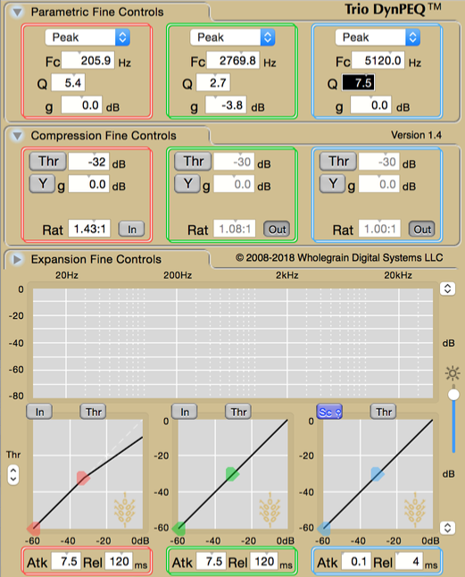
An advantage of parametric EQ is that the presence and shelf filters can be broken down to the weighted sum of a high-, low-, or band-pass filter and unity, which is pass-through. The band-selective filters within the parametric section can be applied to the sidechain signal to monitor the band that the parametric section will operate on. Sidechain search implements this monitoring mode. An alt-click on a band In/Out button activates sidechain search. In sidechain search mode, the coarse tuning display is replaced by the response of band-selective filters modulated by the measured band level for all bands in that mode–with their In/Out buttons showing blue. Without coarse tuning beads, you must perform the find step via fine tuning controls or a control surface. By experience, we find that bands can be more easily found by starting with the Q value higher than normal, in the range of 5 to the maximum.
As you gather experience with sidechain search, we hope you find it a good assistant for ear training. We hope it will help you recognize common acoustic problems more rapidly and lead you to use sidechain search for pinpointing the specific band parameters.
Measure
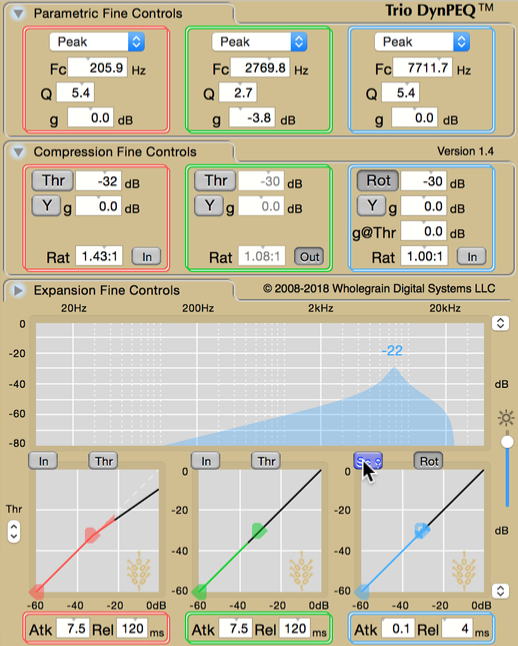
In the sidechain search display, there is a single number associated with each band, representing the maximum level encountered. Once the band of interest has been located, the frequency and Q/slope has been manipulated to the point where the reported level does not likely reflect the level for the band at the end of the find step. Reset the band maximum level by clicking on it while continuing to play the source and let the level indicator increase until it seems to settle. Make a note of this level value, for it should be employed after clicking a blue button to leave sidechain search.
Control
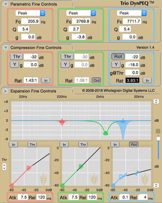
This step takes a little getting used to. The typical use in this context is to reduce the level of this band dynamically, so we wish to apply a compression curve to the band dynamics. We have a decent measurement of the maximum value the band will take, but this is not the level where we wish to put the compression threshold. Instead of estimating where the threshold should be placed, we can define a compression curve that employs the maximum level measurement through rotation point mode, which is activated by clicking on either Thr button for that band.
The rotation point is a fixed pivot through which the compression slope must pass. When the Thr button takes on the Rot label, the level and g offset control the location of the rotation point instead of the threshold. The value opposite of the Rot button in the fine compression controls should be manually set to the maximum level recorded in the measure phase. If you are using a control surface, the label for the rotation point level will still say threshold, so set that value to the recorded level.
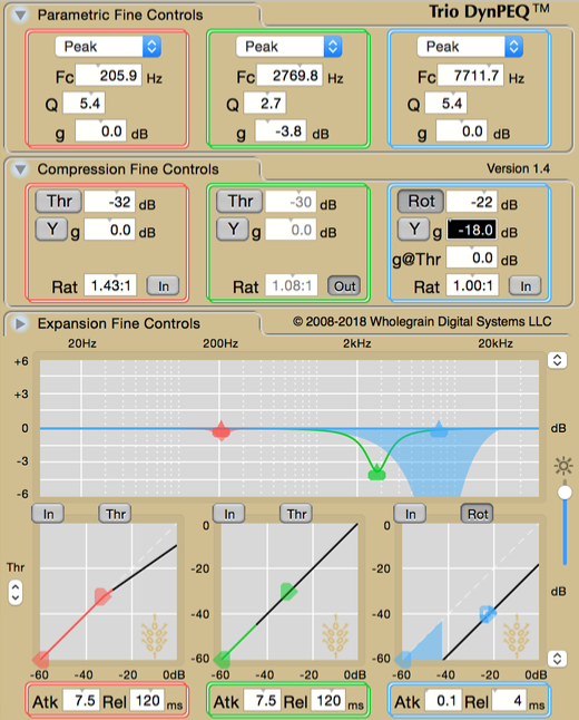
Prior to adjusting the compression ratio, adjust the g offset to the rotation point. This should affect the boost/cut as a constant if the ratio is one–the effect is similar to adjusting the g parameter in the fine tuning controls. In this step, we are looking for a g offset that covers the desired boost/cut at or near the worst case for the band. We find that, with experience, the g offset should be set more aggressively than normal, since we are listening to a fixed boost/cut for all cases good and bad.
Balance
The last step of this process is to adjust the compression ratio for the band, typically upwards if the g offset has been adjusted downwards. The virtual compression threshold is placed where the slope crosses the g@Thr offset, whose default is 0 dB. Raising the ratio typically raises the virtual threshold. The goal is to find the compression ratio where the compression is applied when it is needed.
At this point, you may find it necessary to make slight adjustment to either the g offset or the compression ratio, or refining the control and balance steps. With experience, this should not take much extra time. Using the principles of these two special modes in DynPEQ, administering control on bands of interest should become a routine task.